Physical Address
304 North Cardinal St.
Dorchester Center, MA 02124
Physical Address
304 North Cardinal St.
Dorchester Center, MA 02124

[ad_1]
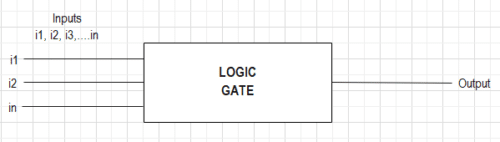
Logic Gates are the inspiration of all digital programs, whether or not combinational or sequential, the circuit follows some logic. In easy phrases, a logic gate is a digital circuit with a number of inputs and a single output. The connection between inputs and output of the logic gate follows a sure logic. This logic sticks to the principles of Boolean Algebra. To develop a deep understanding of logic gates, we must always perceive the fundamentals of digital alerts, binary quantity programs, and Boolean Algebra.
NOTE: There is no such thing as a suggestions loop or reminiscence unit in logic circuits.
An analog sign is a steady time-varying present or voltage sign, whereas a digital sign is a pulsating waveform of two discrete values-high and low. These two discrete values are represented by binary numbers 0 and 1. A digital circuit is an digital circuit that processes digital alerts.
Merely, it’s both a YES or NO, nothing in between.
In digital circuits,
0 = No, False, Change Off, Open Circuit, and Low.
1 = Sure, True, Change On, Closed Circuit, and Excessive.
The decimal system has a base or radix of 10 that means that the quantity is represented by ten digits 0, 1, 2, 3, 4, 5, 6, 7, 8, and 9. Equally, the binary system has a base or radix of two with solely two digits: 0 and 1.
The Binary quantity system represents a quantity both by 0 or 1. For any quantity to be represented in Binary type, it undergoes a binary conversion.
Instance: 1 is 001, 2 is 010, 3 is 011, 4 is 0100, 5 is 0101,… 15 is 1111 and so forth.
An Irish mathematician George Boole developed a mathematical system with the usage of symbols. The system behaves equally to algebra for fixing binary or logic issues.
An equation represented by symbols however follows the legal guidelines of Boolean Algebra is called Boolean Expression.
Three operations utilized in Boolean Algebra are-
1) OR Operation
2) AND Operation
3) NOT Operation
OR Operation is a type of logic addition represented by (+) signal with two or a number of inputs producing one output. The OR Operation produces HIGH output (1) provided that one or all of the inputs to the digital circuit is HIGH (1). If each of the inputs are LOW (0), the output of the digital circuit may even be LOW (0).
Allow us to perceive this with an instance:
Think about a circuit with two switches related in parallel to a LED. The LED can be ON if the present flows via the circuit. For the present to movement, one of many switches should be closed.
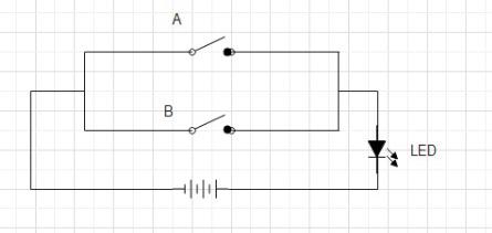
NOTE: WE CAN USE A BULB AS WELL.
Case 1:
Change A=OPEN, Change B= OPEN
If each the switches are open, no present flows via the circuit and the LED doesn’t glow.
Case 2:
Change A=OPEN, Change B=CLOSED
As a result of parallel connection, even when one of many switches is closed and the opposite is open, present flows via the circuit. This causes the LED to glow.
Case 3:
Change A=CLOSED, Change B= OPEN
Present flows via the circuit, and the LED glows
Case 4:
Change A=CLOSED, Change B= CLOSED
If each the switches are closed, excessive present flows via the circuit, and the LED glows.
| SNO | SWITCH A | SWITCH B | LED |
| CASE 1 | OPEN | OPEN | OFF |
| CASE 2 | OPEN | CLOSED | ON |
| CASE 3 | CLOSED | OPEN | ON |
| CASE 4 | CLOSED | CLOSED | ON |
The Boolean expression for OR Operation is
Y= A + B
The place Y= Output; A= Enter 1; B= Enter 2
AND Operation is a type of logic multiplication represented by the (.) signal with two or a number of inputs producing a single output. The AND Operation produces HIGH output (1) provided that all of the inputs to the digital circuit are HIGH (1). If one or each of the inputs are LOW (0), the output of the digital circuit may even be LOW (0).
Allow us to perceive this with an instance:
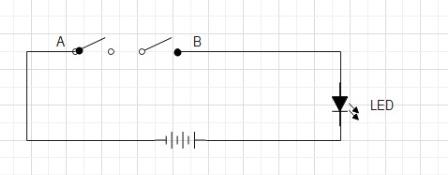
Think about a circuit with two switches related in collection to a LED. The LED can be ON if the present flows via the circuit. For the present to movement, each of the switches should be closed. If both one of many switches is open, the present won’t movement.
Case 1:
Change A=OPEN, Change B= OPEN
As each the switches are open, the present doesn’t movement via the circuit and the LED doesn’t glow.
Case 2:
Change A=OPEN, Change B=CLOSED
If one of many switches is open in a series-connection circuit, it’s not possible for the present to movement. Therefore, LED doesn’t glow.
Case 3:
Change A=CLOSED, Change B= OPEN
If one of many switches is open, the present doesn’t movement via the circuit and the LED doesn’t glow.
Case 4:
Change A=CLOSED, Change B= CLOSED
If each the switches are closed, a excessive present flows via the circuit, and the LED glows.
| SNO | SWITCH A | SWITCH B | LED |
| CASE 1 | OPEN | OPEN | OFF |
| CASE 2 | OPEN | CLOSED | OFF |
| CASE 3 | CLOSED | OPEN | OFF |
| CASE 4 | CLOSED | CLOSED | ON |
The Boolean expression for AND Operation is
Y= A . B
Principally, the dot (.) is eliminated
Y= AB
The place Y= Output; A= Enter 1; B= Enter 2
NOT is an Operation within the type of logic inversion, referred to as a complement. There’s a single enter producing the one output. NOT operation produces a HIGH (1) output for a LOW (0) enter and a LOW (0) output for a HIGH (1) enter.
It’s represented by a bar (ˉ) over the variable.
Allow us to perceive this with an instance:
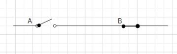
Think about a ganged swap. If one of many switches is open, the opposite is mechanically closed and vice versa.
| SWITCH A | SWITCH B |
| OPEN | CLOSED |
| CLOSED | OPEN |
The Boolean expression for NOT Operation is
Y= Aˉ
The place Y= Output; A= Enter
A logic gate is a digital circuit with a single output whose worth relies upon upon the logical relationship between the enter(s) and output. In easy phrases, The connection between the enter values and the output relies on a sure ‘logic’, therefore these circuits are addressed as logic gates. The logic gates have just one output for single enter or variety of inputs. To know the operation of a logic gate, a Reality Desk is ready by stating all of the mixtures of inputs along with the output.
There are 3 forms of logic gates-
1) Primary Gates: OR, AND, and NOT Gates.
2) Common Gates: NAND, and NOR Gates.
3) Derived Gates: XOR Gates, and XNOR Gates.
Let’s perceive all three logic gates in deep.
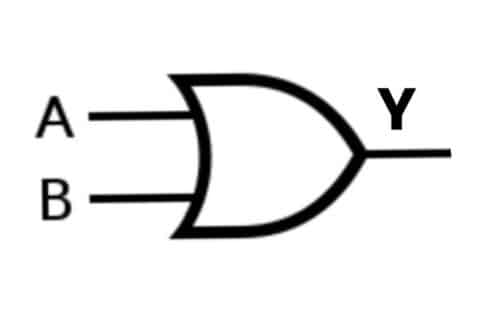
There are three forms of primary logic gates- OR, AND, and NOT gates. A Primary logic gate behaves the identical because the corresponding logic operator.
The logical expression for an OR Gate is
Y= A OR B
Case 1: A= 0, B= 0; Y= 0
On this case, each the inputs are LOW (O), so the OR Gate produces LOW (0) output.
Case 2: A= 0, B= 1; Y= 1
On this case, one of many inputs is HIGH (1), so the OR Gate produces the HIGH (1) output.
Case 3: A= 1, B= 0; Y= 1
On this case, one of many inputs is HIGH (1), so the OR Gate produces the HIGH (1) output.
Case 4: A= 1, B= 1; Y= 1
On this case, each the inputs are HIGH (1), therefore the OR Gate produces the HIGH (1) output.
OR Gate Reality Desk:
| A | B | Y=A OR B |
| 0 | 0 | 0 |
| 0 | 1 | 1 |
| 1 | 0 | 1 |
| 1 | 1 | 1 |
The logical expression for an AND Gate is
Y= A AND B

Case 1: A= 0, B= 0; Y= 0
On this case, each the inputs are LOW (O), so the AND Gate produces LOW (0) output.
Case 2: A= 0, B= 1; Y= 0
On this case, one of many inputs is LOW (0), therefore the AND Gate produces a LOW (0) output.
Case 3: A= 1, B= 0; Y= 0
On this case, one of many inputs is LOW (0), so the AND Gate produces a LOW (0) output.
Case 4: A= 1, B= 1; Y= 1
On this case, each the inputs are HIGH (1), the AND Gate produces HIGH (1) output.
AND Gate Reality Desk:
| A | B | Y=A AND B |
| 0 | 0 | 0 |
| 0 | 1 | 0 |
| 1 | 0 | 0 |
| 1 | 1 | 1 |
The logic expression for a NOT Gate is
Y=Aˉ
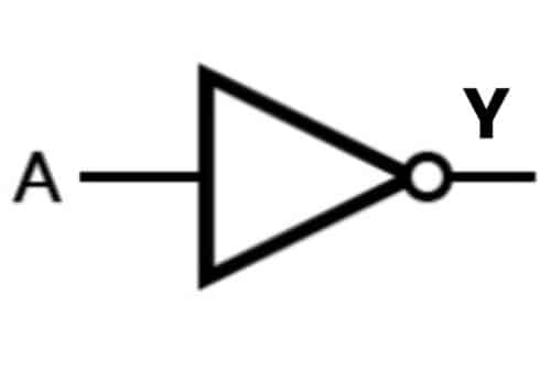
Case 1: A=0; Y= 1
The enter of the NOT gate is LOW (0), the output turns into HIGH (1).
Case 2: A=1; Y= 0
The enter of the NOT gate is HIGH (1), so the output turns into LOW (0).
NOT Gate Reality Desk:
The Common Logic Gates can implement any Boolean expression by itself, this implies they don’t require some other gate for implementation. A single Common Logic Gate is able to constructing a logic circuit. There are two forms of Common Logic Gates
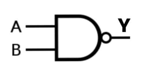
A NAND Gate is a complement of AND Gate or just, a mixture of NOT Gate and AND Gate. It’s known as NAND as N stands for NOT, that means a NOT AND Gate. For 2 or extra inputs, the NAND gate produces a HIGH (1) output provided that one of many inputs is LOW (0).
The NAND Gate Boolean Expression is denoted by a complement of AND.
Y= (AB)ˉ
Case 1: A= 0, B= 0; Y= 1
On this case, each the inputs are LOW (O), the NAND Gate produces HIGH (1) output.
Case 2: A= 0, B= 1; Y= 1
On this case, one of many inputs is LOW (0), the NAND Gate produces a HIGH (1) output.
Case 3: A= 1, B= 0; Y= 1
On this case, one of many inputs is LOW (0), the NAND Gate produces a HIGH (1) output.
Case 4: A= 1, B= 1; Y= 0
On this case, each the inputs are HIGH (1), the NAND Gate produces LOW (0) output.
NAND Gate Reality Desk:
| A | B | Y=A NAND B |
| 0 | 0 | 1 |
| 0 | 1 | 1 |
| 1 | 0 | 1 |
| 1 | 1 | 0 |
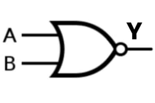
A NOR Gate is a complement of OR Gate or a mixture of NOT Gate and OR Gate. It’s known as NOR as N stands for NOT, that means a NOT OR Gate. For 2 or extra inputs, the NOR gate produces a HIGH (1) output; solely each inputs are LOW (0).
The NOR Gate Boolean expression is denoted by a complement of OR.
Y= (A+B)ˉ
Case 1: A= 0, B= 0; Y= 1
On this case, each the inputs are LOW (O), the NOR Gate produces HIGH (1) output.
Case 2: A= 0, B= 1; Y= 0
On this case, one of many inputs is HIGH (1), the NOR Gate produces the LOW (0) output.
Case 3: A= 1, B= 0; Y= 0
On this case, one of many inputs is HIGH (1), the NOR Gate produces the LOW (0) output.
Case 4: A= 1, B= 1; Y= 0
On this case, each the inputs are HIGH (1), the NOR Gate produces the LOW (0) output.
NOR Gate Reality Desk:
| A | B | Y=A NOR B |
| 0 | 0 | 1 |
| 0 | 1 | 0 |
| 1 | 0 | 0 |
| 1 | 1 | 0 |
The derived or particular gates are made for particular purposes akin to half adders, full adders, and subtractors. There are two derived logic gates comprised of OR and NOR gates.
Ex-OR gate has two or extra inputs however a single output. Ex-OR gate generates a HIGH (1) output if each the inputs are usually not on the identical logic degree A≠B.
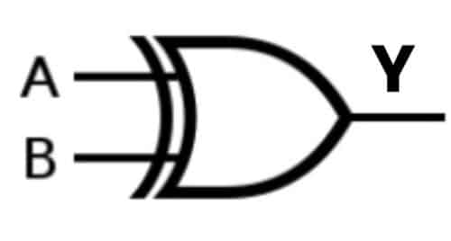
Case 1: A= 0, B= 0; Y= 0
On this case, each the inputs are LOW (O) on the identical logic degree. Because of this, the Ex-OR Gate produces a LOW (0) output.
Case 2: A= 0, B= 1; Y= 1
On this case, one of many inputs is LOW (0) and the opposite is HIGH (1). Therefore, they aren’t on the identical logic degree. Because of this, the Ex-OR Gate produces the HIGH (1) output.
Case 3: A= 1, B= 0; Y= 1
On this case, one of many inputs is HIGH (1) and the opposite is LOW (0). Therefore, they aren’t on the identical logic degree. TAs a outcome, the Ex-OR Gate produces the HIGH (1) output.
Case 4: A= 1, B= 1; Y= 0
On this case, each the inputs are HIGH (1) on the identical logic degree. Because of this, the Ex-OR Gate produces the LOW (0) output.
XOR Gate Reality Desk:
| A | B | Y=A XOR B |
| 0 | 0 | 0 |
| 0 | 1 | 1 |
| 1 | 0 | 1 |
| 1 | 1 | 0 |
EX-NOR gate has two or extra inputs however a single output. EX-NOR gate generates a HIGH (1) output if each the inputs are on the identical logic degree A=B.
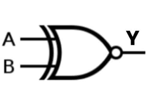
Case 1: A= 0, B= 0; Y= 1
On this case, each the inputs are LOW (O) on the identical logic degree. Because of this, the EX-NOR Gate produces HIGH (1) output.
Case 2: A= 0, B= 1; Y= 0
On this case, one of many inputs is LOW (0) and the opposite is HIGH (1). Therefore, they aren’t on the identical logic degree. Because of this, the EX-NOR Gate produces the LOW (0) output.
Case 3: A= 1, B= 0; Y= 0
On this case, one of many inputs is HIGH (1) and the opposite is LOW (0). Therefore, they aren’t on the identical logic degree. Because of this, The EX-NOR Gate produces the LOW (0) output.
Case 4: A= 1, B= 1; Y= 1
On this case, each the inputs are HIGH (1) on the identical logic degree. Because of this, the EX-NOR Gate produces the HIGH (1) output.
XNOR Gate Reality Desk:
| A | B | Y=A XNOR B |
| 0 | 0 | 1 |
| 0 | 1 | 0 |
| 1 | 0 | 0 |
| 1 | 1 | 1 |
We hope now you could have a transparent concept about all of the Logic Gates. However if in case you have any doubt, be happy to remark beneath. Or you should utilize our Discussion board to attach with our Engineers.
[ad_2]