Physical Address
304 North Cardinal St.
Dorchester Center, MA 02124
Physical Address
304 North Cardinal St.
Dorchester Center, MA 02124

[ad_1]
 This information logging system can be utilized to interface an exterior or inside sensor of Raspberry Pi Pico board. The venture has many benefits, together with the usage of inside temperature sensor of Raspberry Pi Pico board; so an exterior temperature sensor will not be required. Second, the simply removable microSD card can be utilized to document completely different temperature information at a specific place or industrial setup. The SD card might be eliminated and carried to laboratory or management room for evaluation or future reference. The venture additionally contains non-obligatory exterior sensors, reminiscent of drive and light-weight sensors.
Parts required for the venture are given within the Desk beneath.
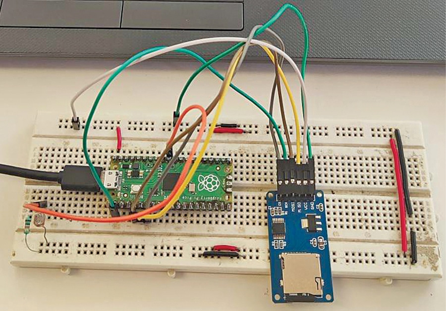
The creator’s prototype wired on the breadboard is proven in Fig. 1 and the connection of knowledge logging system with microSD card and Raspberry Pi Pico is proven in Fig. 2. An LDR or some other appropriate analogue sensor, such because the drive sensor proven, could also be used.
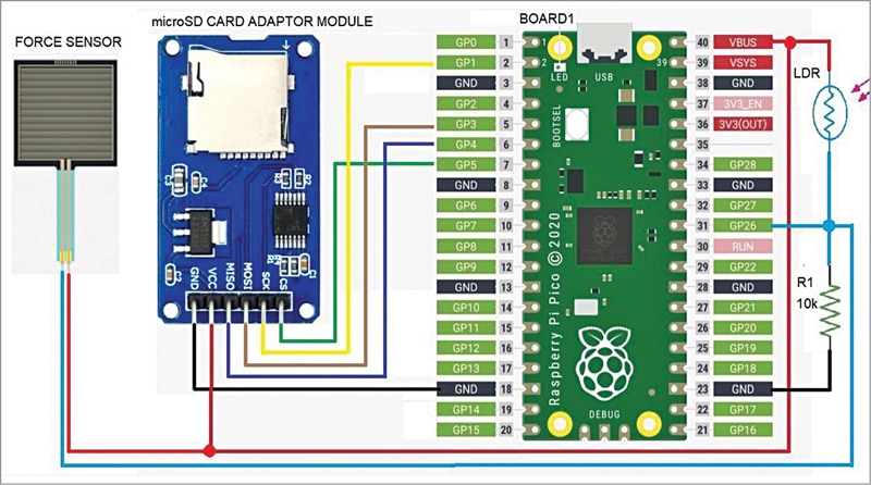
The setup makes use of serial peripheral interface (SPI) pins MOSI, MISO, CS, and CLK of Raspberry Pi Pico Board1. Exterior sensor (mild sensor, mild dependent resistor, or drive sensor) is related to GP26 pin of Board1.
LDR sensor is used to document mild situation within the space the place it’s put in. The microSD card module is interfaced with Raspberry Pi Pico board pins GP1, GP3, GP4, and GP5. VBUS from the board is used as energy provide for microSD card and LDR. A 10k pull-down resistor is related to GP26 pin of Board1 for interfacing exterior sensors.
The venture is managed by the Python program developed on Mu editor. Mu editor is a straightforward code editor that works with Adafruit CircuitPython boards, together with Raspberry Pi Pico, and on most working methods, together with Home windows and Linux. CircuitPython relies on Python programming language and is simple to grasp.
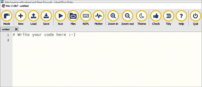
Each Mu and CircuitPython are required for this venture. Mu editor might be downloaded from https://codewith.mu after which put in utilizing directions given at hyperlink. After putting in Mu editor, run it and you will notice the window proven in Fig. 3.
CircuitPython model 7.1.1 was used throughout testing of this venture. CircuitPython board requires a bootloader referred to as UF2 (USB flashing format) that makes putting in and updating CircuitPython a fast and straightforward course of. Obtain the newest model of CircuitPython bootloader .UF2 file from click on this hyperlink.
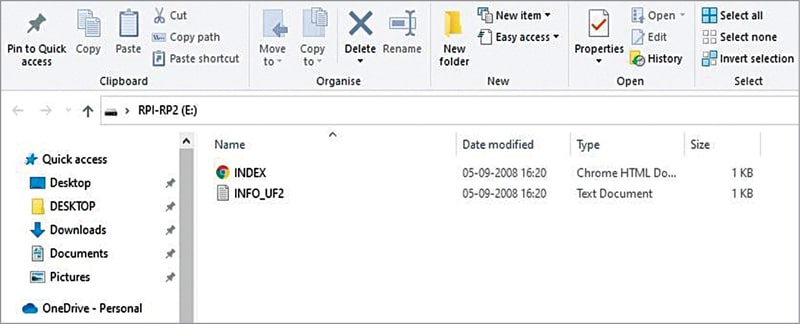
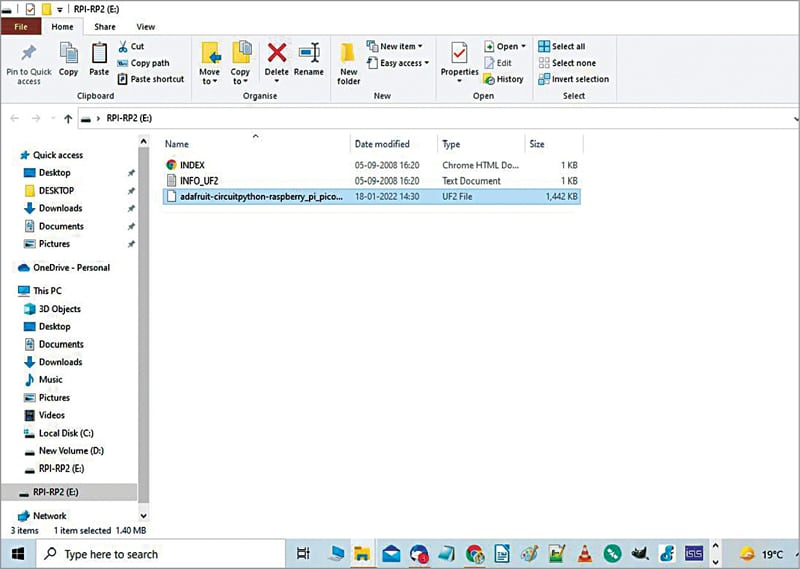
Putting in CircuitPython on the board is simple. Simply copy and paste the file as defined right here. First press the BOOTSEL button on the Raspberry Pi Pico board, whereas inserting the USB cable of the RPI board to laptop computer/PC, and launch it after a brand new drive (RPI-RP2) window seems, as proven in Fig. 4.
Subsequent, copy adafruit-circuitpython-raspberry_pi_pico-en_US-7.1.1.uf2 file downloaded in earlier step. Paste it into the brand new window, as proven in Fig. 5. Now open Mu editor window and shut all different home windows.
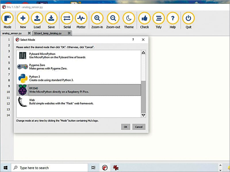
Subsequent, the very first thing to do in Mu is to pick out ‘Mode’ from the primary menu. On this venture, it’s best to choose RP2040 possibility in Choose Mode window, as proven in Fig. 6.
Begin coding on the Mu editor window or load the prevailing code. You’ll be able to load the analog_sensor.py code that comes together with this venture. This code will work with both LDR or drive sensor however not with each on the identical time.
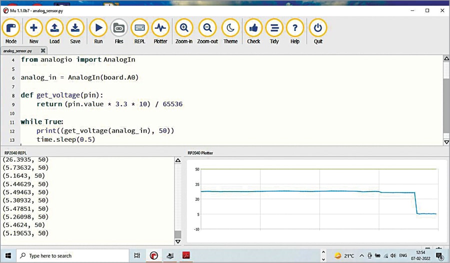
Join LDR to the circuit, as proven within the schematic, and run the code by clicking Run button. While you cowl the LDR with an opaque object and uncover it once more, you will notice the sunshine depth’s arbitrary values fluctuate between 0 and 32, with 0 being the darkest and 32 being the brightest mild.
A further function of Mu is its means to show the information waveform. When you choose the Plotter possibility from the primary menu, you will notice the output waveform, as proven in Fig. 7. Equally, you possibly can exchange LDR with some other analogue sensor like drive sensor. The sensor information will likely be displayed on the display together with the waveform.
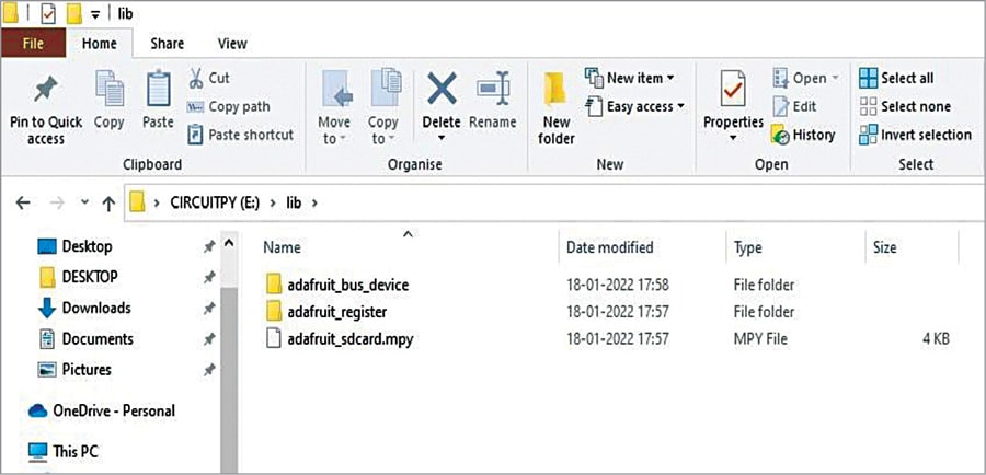
Allow us to now discover the inbuilt temperature sensor on Raspberry Pi Pico board and retailer the temperature information on the microSD card that’s usually utilized in your cell phone. Right here, we use CircuitPython libraries together with the primary code (Sdcard_temp_data.py). That you must import adafruit libraries for SD card to interface it with the Raspberry Pi Pico board. For that obtain the libraries (Bundle for Model 7.x) from this hyperlink.
Unzip the Bundle folder and duplicate adafruit_bus_device and adafruit_register folders, paste them into ‘lib’ folder in CIRCUITPY(E) drive. Additionally copy adafruit_sdcard.mpy file from the Bundle folder and paste into ‘lib’ folder, as proven in Fig. 8.
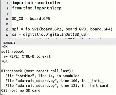
Open Mu editor and cargo the primary code below Code.py file. Save the file and run it. If one thing goes fallacious, you’re going to get error message on the backside of the Mu editor window. For instance, if SD card will not be related correctly to the circuit, you’re going to get “OSError: no SD card” error message, as proven in Fig. 9.
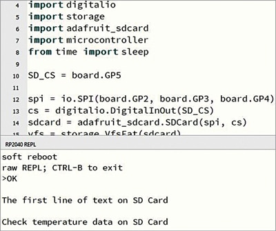
If all the pieces is okay, as a substitute of error message you will notice following textual content (see Fig. 10) beneath the Mu editor window: “The primary line of textual content on SD card, Test temperature information on SD card”
Now, give up Mu editor and unplug the SD card from its adaptor. Insert SD card into the microSD card slot in your laptop computer/PC and verify the assorted temperature values obtainable in textual content file format.
The entire circuit might be assembled on a breadboard or general-purpose PCB. Most Raspberry Pi Pico boards don’t include header pins related or soldered on the boards. With out these pins, the board can’t be interfaced with exterior units, reminiscent of sensors, motors, or any gadget required for the venture. Wires might be soldered instantly onto the holes offered on the board, however that could be a bit dangerous as you could injury the board.
So, to entry GPIO pins, solder every pin fastidiously utilizing male Berg strip connectors with an applicable soldering iron. You’ll be able to then both mount the pins on the breadboard or join every pin with jumper wire to different parts or modules.
In spite of everything connections are carried out, recheck right polarities, specifically Vcc and floor pins. Word that VBUS at pin 40 is often 5V, which is the primary Vcc provide within the circuit. Earlier than inserting the microSD card first format it in FAT32 system and solely then insert it into the slot offered within the adaptor.
While you plug in your Raspberry Pi Pico to your laptop computer the primary time, Mu editor makes an attempt to auto-detect your board on start-up and searches for CIRCUITPY drive within the board. So, previous to this, make sure that CircuitPython is correctly put in within the drive, as defined above. Subsequent, choose the mode and run the code analog_sensor.py.
When you get correct sensor output information and waveform, open the primary code by clicking on Load possibility on the primary menu bar. Run the code and be sure to get the output message on the backside of the Mu editor window. You’ll be able to give up this system and swap off the circuit any time you want to verify the sensor information on the SD card from any pc having microSD card slot.
Sani Theo is an electronics fanatic, circuit designer, and technical editor
[ad_2]